NTS offers Non-destructive Testing (NDT) by the use of 2D/3D X-ray imaging, X-ray/CT metrology or computed tomography (CT) imaging. These methods are used to evaluate the properties of components, systems or materials without causing structural damage or contamination to the items in question. This technique also allows for inspection of hidden features within an assembly that may otherwise be overlooked with other visual/surface based imaging techniques.The many benefits of using X-Ray/CT for NDT include:

The NDT technique of X-Ray/CT is commonly used in the industries of defense, aerospace, additive manufacturing, electronics and forensics.
There are two main types of X-ray/CT imaging, each with its own specialized use. They include:
Digital radiography (DR) makes use of a digital detector to acquire X-Ray images in real time. This is an improvement over the traditional film-based technique which can be cumbersome and lack dynamic range within an image.The digital format means that the data is easily manipulated with specialized software, there is no need to analyze film and/or convert to a digital format where image quality can suffer.
3D X-ray imaging uses a collection of 2D X-rays acquired 360 degrees around an object in order to create a 3D reconstruction. The 3D reconstruction is then viewed by “slicing” through the object with unique software, cross sections from any angle or depth inside of the object can be seen.

X-Ray or Digital Radiography is the imaging of an object using a single X-Ray with a digital panel. The results are captured and presented in two dimensions (2D) as a flat image. X-Ray inspection is generally a quicker approach and involves less setup.Computed Tomography utilizes identical equipment, however a rotation stage is added and approximately 3000 X-Rays are acquired while the object rotates around 360 degrees. All of these X-Ray projections are then reconstructed into a 3D model. The data is then presented in three dimensions (3D) as volume data.
The main inspection and analysis uses for CT scanning include:
Internal/External components can be imaged using CT scanning. The overall quality and fit of each component can be assessed by viewing the individual CT scan slices of the object. Digital calipers can be used in the software to measure offsets, locations or specified distances within the object.
Modern manufacturing techniques require the use of a CAD model in conjunction with a technical drawing as the root of any design. CT Scan data can be directly compared to any major CAD format allowing for a 100% inspection of each interior/exterior surface. Likewise, scans can be compared to other scans in order to assess variation of products with the same type or intended design.

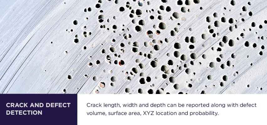
There are a number non-destructive (as well as destructive) methods for determining porosity/defect statistics and crack propagation. Most of these methods require disassembly of an object and the use of a penetrant that will leave residue within the object. CT scanning uses the density of the material to gather information and does not require any disassembly or penetrant to be added. By using the density gradients, cracks and defects/porosity can be segmented out and quantified. Crack length, width and depth can be reported along with defect volume, surface area, XYZ location and probability.
Legacy or obsolete components often lack a digital drawing or CAD model at the source. Complex objects that contain hidden surfaces can be CT Scanned and reverse engineered into a CAD model, providing a means to efficiently and consistently reproduce a legacy or obsolete component. CT scan data sets can be directly converted to point clouds, STL or mesh data. From this mesh or point cloud data, CAD native files can be created (STP, IGES, etc.).Finite Element Analysis (FEA) is typically performed on the original CAD design of an object. CT Scanning captures the “as built” component and produces a CAD file that can be used with FEA. Performing FEA on an “as built” object can help determine whether any deviations from intended design will have an effect on the expected performance.
Similar to laser scanning or touch probe coordinate measurement machine (CMM) technology, the surface extractions from CT scan data allow for geometric dimensioning and tolerance. When performing a CT scan for the purposes of CT Metrology, a calibrated artifact is used within the scan to verify the accuracy of the scan resolution. Dimensional call outs can be performed on the CT scan data in accordance with a drawing or specification/standard.

In-Situ CT Scanning is the process of performing 3D X-Ray/CT scans on an object in its “as used” state, or “in situation”. CT scanning objects when they are subject to a mechanical/electrical load can give insight to verify whether the object is functioning as expected. This technique is widely used in composites with stresses or loads applied at several intervals. Cracking and broken fibers can be recorded and tracked throughout a series of increasing loads. Likewise, mechanical operations inside of an object can be observed and measured.
Composite samples often use complex layer make-ups and orientations to provide strength for various applications. The details of each layer including the fiber orientation, diameter and volume are all critical to the performance of the design. CT Scanning allows for each layer to be analyzed individually, providing statistics on broken fibers, fiber angle and fiber volume. Quantifying these values on a layer by layer basis helps create models that can anticipate where and when a failure might occur.