
By Jeff Viel, Regional Director of EMI Engineering ServicesSimply stated, the term HERO stands for the common effects of and Hazards of Electromagnetic Radiation to Ordnance. Ordnance can be categorized as an Explosive, chemical, or pyrotechnic devices used in equipment such as bombs, rockets, and ammunition carried on airborne, sea, space, or ground systems. These hazards exist due to a fundamental incompatibility between firing circuits contained within ordnance systems, and the external radiated electromagnetic environment (EME) they encounter during deployment. When sufficient amount of energy is coupled into the firing mechanism to cause unintentional or premature operation, safety and reliability consequences exist. Accidental EID activation can jeopardize safety through unintentional initiation of explosive trains, or on reliability through duding (EIDs can no longer perform their intended function, thus rendering the system incapable of performing its mission). In either case HERO consequences can lead to disastrous results.Currently, MIL-STD-464 requires all branches of the DoD to ensure that ordnance is designed to provide sufficient immunity from its expected EME prior to deployment, and verified by testing and analysis. The general approach for a HERO evaluation is to expose inert, instrumented ordnance to a controlled test electromagnetic environment and to monitor the explosive initiation device (EID) contained within the ordnance for a possible response. For most EIDs, the response is quantified in terms of the amount of RF current induced into the heating element, or bridgewire, of the device.A common objective in all HERO testing is to determine the maximum or worst case response at each test frequency for various ordnance configuration phases (i.e., transportation and storage, assembly and disassembly, handling/loading, and platform loaded). These are also known as the stage to stockpile or “S4” phases. The general approach is to establish a desired test EME level at a selected test frequency while measuring the induced current. Specific test procedures may vary according to the type of test facility being used, for example, an open-air site, a mode-stirred chamber, or an anechoic chamber.MIL-STD-464 defines the HERO frequency and field strength levels for all HERO tests.The HERO test levels are provided for “Unrestricted” and “restricted” locations. The “Unrestricted” levels are intended for ship launched ordnance that will traverse the main beam of transmitters in the 2.7 GHz to 3.6 GHz reaching peak fields of 27,460 V/m. For all other ordnance the unrestricted peak field level in this frequency band is reduced to 12,667 V/m, with an average field level of 1,553 V/m. The “Restricted” levels are intended for ordnance areas where personnel may be present such as assembly/disassembly and loading/unloading areas. In order to for an ordnance manufacturer to obtain a “HERO SAFE ORDNANCE” at the all-up round or appropriate assembly level, the ordnance must be evaluated against these test levels.For most HERO testing, the average EME is the primary concern because the majority of bridgewire EIDs have relatively long response times (tens of milliseconds) when compared to common pulse modulation duty cycles. In such cases, the magnitude of the induced EID current is equal when exposed to either PM or CW field modulations.However, EIDs that exhibit extremely fast response times such as Conductive composition primers may react to a single pulse or, as in thermal stacking, gradually respond over time to repeated pulses, as in a pulse train. If it is determined that the EID can respond to peak EME levels for single pulses or from thermal stacking, the test EME must include the peak levels specified in MIL-STD-464.It is not uncommon for test laboratories to struggle with achieving the unrestricted peak field, or even average field levels within all of the specified frequency bands. However, HERO testing may be performed a reduced levels by utilizing the field extrapolation method described in MIL-HDBK-240. This entails of a commonly accepted practice of measuring the response of the EID at the maximum achievable field intensity and extrapolating those measurements to determine the Maximum Allowable Environment (MAE) the EID can be exposed to before reaching its Maximum No Fire current (MNFC) value. The extrapolation method is also used to determine the maximum level which ordnance can be safety certified in order to facilitate the safe handling of the item in higher environments should the need arise in the future.In order for the field extrapolation method to yield valid results, there must be some reasonable evidence that the EID circuits respond linearly to the applied field. Also, the induced current measurement instrumentation must be sensitive enough to detect a current level less than the EIDs specified Maximum No Fire Current level when multiplied by the ratio value of the required field to the test field, and further reduced by a Firing Consequence Factor of 16.5 dB (Safety margin), and/or 6 dB (reliability margin).If both of these conditions are met, HERO test data can be gathered at levels readily available by the test facility and extrapolated to determine the ordnance MAE. Figure I. depicts a typical extrapolation worksheet developed by NTS.
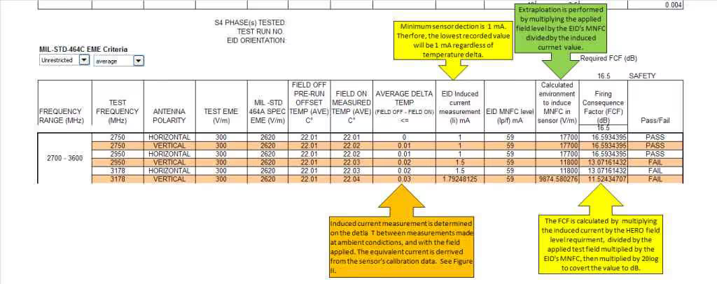
Figure 1

Example of thermal sensor installation onto bridgewire
NTS Commonly uses fiber optic thermal couple arrays when conducting HERO evaluations. These sensors are carefully calibrated to correlate temperature to current flow through the EID bridgewire. This requires the sensor to be installed on the EID (as shown in Figure III), then applying a calibrated current source over the bridgewire at discrete steps up to the EID MNFC value. Figure II (below) provides an example calibration data for a thermal sensor.
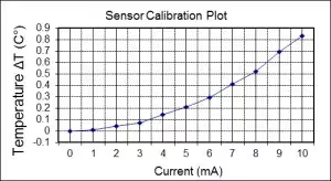
Figure II Typical thermal sensor calibration data

Figure III Standard Fiber Optic Thermal Sensor Installation (Click for larger view

Chemring M35 Flares for HERO testing
The plot clearly shows a correlation between induced current and temperature. The minimum detectable current will be dependent on the sensors minimal detectable temperature, and the lowest current value applied during the sensor calibration. In accordance with MIL-HDBK-240, at any point during the test where temperature delta readings fall below the sensors minimum detectable level and/or below the minimum calibration point, the minimum detectable current level of the sensor shall be recorded. In some cases, this may require the test lab to increase the applied field level or even achieve the HERO specified test level in order to properly validate the MAE, while maintaining the appropriate Firing Consequence Factor (either 16.5 dBor 6 dB).
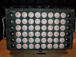
Chemring M34 Flares launcher loaded configuration
As discussed, the general approach for HERO testing is to expose inert, instrumented ordnance to a controlled test EME and to monitor each EID contained within the ordnance for a possible response. For most EIDs, the response is quantified in terms of the magnitude of RF current induced into the heating element, or bridgewire, of the device. However, Go/No-Go type verification tests may be necessary when EID instrumentation is not feasible. This brute force approach can be costly, requiring a significant number of samples, extensive test time, and high-powered EME generation equipment to properly evaluate systems and should only be performed when necessary.Reasonable test results can be obtained with Go/No-Go techniques using either a safety/reliability margin verification test or a statistical sample size verification test. Both methods require that the test facility have the capability to test EME levels at or above the required EME criteria levels.
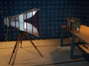
Chemring M34 Flares in launcher configuration during HERO Test 200 MHz - 1 GHz
The safety/reliability margin verification method requires exposing the SUT to EME levels that are higher than the criteria EME levels by the appropriate margin (either 16.5 dB for safety, or 6 dB for reliability FCF). The ordnance should be loaded with at least the minimum explosives needed to represent the production unit. In most cases, a large number of EID types would be required for testing. EIDs are typically replaced following each test range or orientation in an effort to prevent over stressing the ordnance due to repeated RF exposure.The statistical sample size verification test calls for exposure of a large number of EID samples to each set of test conditions. The number of fires to no-fires statistically demonstrates compliance with the required margins and confidence levels. Thus, many test runs will have to be performed on a number of test samples for a given set of conditions. For example, to demonstrate a reliability of 85 percent and a confidence level of 80 percent, a sample size of 10 EIDs would be required. The main difference between this method and the safety/reliability method is that testing is conducted at the required field level, and not increased by the FCF.
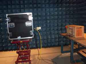
Chemring M34 Flares in Crated configuration during HERO test 12 GHz - 18 GHz
NTS is provides full compliance service offering to MIL-STD-461 specifically exceeding the maximum field generation requirements specified in RS103 from 10 kHz to 40 GHz. Additionally, NTS is fully equipped with field generating equipment capable of achieving the commercial aerospace HIRF requirements up to Category L per RTCA DO160, which represents some of the most severe electromagnetic environments required in commercial aircraft compliance today.In summary, NTS is equipped to perform HERO test evaluations utilizing the test methods in accordance with but not limited to the latest revisions of MIL-STD-464, MIL-STD 331, and MIL-HDBK 240.For more information regarding NTS capabilities or HERO testing, please contact the NTS Eastern Region Quotations team:1146 Massachusetts AvenueBoxborough, MA 01719

Chemring M35 Flares Uncrated configuration during HERO Test 4GHz – 8 GHz
978-266-1001easternregionquotations@nts.com